Monday, 30 January 2012

Piecing the Character Together

Now that all of the sections of my character had been created I could now merge them all into one scene and begin to place ad align them together.


This process was moderately difficult; this was due to the fact that all of the sections had been created in separate scenes. Some sectors required some scaling and minor modifying to ensure all of the sections fitted correctly.  

Once turbo smooth was added and rendered as a draft model:


Creating the Trousers

The trousers were created from a cylinder. An image of a pair of trousers was placed on to the scene on a plane.


The cylinder was then converted to an editable poly and the vertices could now be shaped using the outline of the trousers in the image as a guide

By duplicating the cylinder I could now create the other side of the trousers and these two cylinders were then welded together, firstly by attaching them.

To create the creases in the trousers I played around, moving and shaping the vertices to give the trousers a more realistic look.

A material was then created for the trousers. This was done by using a Unwrap UVW modifier. It was necessary to pull out the vertices in the edit mode to shape the trousers to that the material would fit properly.

I then rendered the UVW image to import to Photoshop.

In Photoshop I then took sections of a pair of trousers and slowly built up a pair that I could use as the material for my trousers.   

Once completed the material could now be applied to the trousers.


Creating the Head

The head began its life by creating a cylinder on the scene.


The entire head was designed on the basis of my research and was created using an image as an outline.

I pulled out sectors of the head to create the eyebrows, nose and mouth.

Only half of the head was created at this stage so that I could then duplicate it and weld the other side together. This would ensure I had a symmetrical head.

The ears are created from a cone, converted to an editable polygon and using insets the centre of the ear was made. The ear could now be welded onto the head.


The eyes were created in a tutorial and were made using spheres with a space wrap added to them. The space wrap enables me to shape the eyes while still having control over moving the spheres to open and close the eye lids. A handy technique when it comes to animating.

Shaping the eyes:

An Unwrap UVW was then applied to the head to create an image of the rendered UVW. This was then placed into Photoshop so that I could now create the skin material with the blacked out eyes.

This gives the character a more villain look and covers some of his face.


Creating the Sword

The sword is constructed from just one cylinder. The process began with placing an image of a sword on to the scene on a plane.

Converting the cylinder to an editable poly enabled me to begin to pull out the vertices. The entire handle was created in the same process and all from this one cylinder.

To create the outer wings on the handle these were also created from a cylinder and using the image was a guide I pulled the vertices out to create the shaping of the sword wings. Extra sections had to be added to this cylinder in order to create this complex shape before converting the cylinder to an editable poly.

Once the top of the sword was now completed I could begin to weld it all together. Sections of the sword were duplicated to create symmetrical sectors.

The blade was created in the same process as the handle, dragging out the end polygon and the moving and shaping the vertices in-line with the blade of the image.

To create the material I selected the poly I wanted the selected material to be placed on and then detached these polygons. This process was much easier and quicker than using a Unwrap UVW modifier due to the complex shaping.


Creating the Shoulder Pads

To create the shoulder pads I placed a Cylinder onto the scene, converted it to an editable poly and removed 50% of the polys to leave me with just half excluding the 2 ends.

I could now shape the shoulder pad into a more realistic shape, by creating insets in the polygons I could make indents in the shaping.


It was also necessary to create a double edge around the shoulder pad, this process was done by duplictaing the shoulder pad and the welding the borders together.

The spikes are just cones attached to the newly shaped shoulder pad. These spikes are not welded on as it would have disrupted the shaping of the shoulder pad.
A metal material was now applied to the shoulder pad and the gloss adjusted to maximum in the material editor panel.

Creating the Arm

To create the hand I placed an image of a hand onto a plane in the scene. Using a box converted to an editable poly I could now pull out the vertices to shape the hand.

To create the fingers I had to create new boxes and shape these by pulling out the vertices in line with the fingers on the image. For each finger I copied last finger and modified it as necessary to create new fingers.


Once all of the palm and fingers including thumb had been created I then had to remove selected polygons on the palm and at the end of the fingers. This would then allow me to be able to weld the fingers to the palm.

At this stage the hand appeared slightly flat and required shaping around the edges as it looked very square. This part of the process required me to move the vertices and place them in positions via freehand.

The hand was now beginning to look very realistic at this stage.

The easiest part was to create the arm. This was created by selecting the border of the opening of the palm and while holding the shift key I could now drag out the edge and create the arm, stopping and restarting to make stages in the arm such as the joints etc. By fine adjusting the vertices I could now shape the arm to give it more realistic shape.


A material could now be applied to the arm and hand. The selected material was an image of a skin texture.

Sunday, 29 January 2012

Creating the Boot

To create the boot I used a similar process as the top of the body. In this process I did require me to develop much of the boot using freehand creation.


The base of the boot was the first to be created. This was done by first placing a bitmap image onto a plane and using a box with several edges on width, height and length placed on top.

By converting the box to an editable poly I could now pull the vertex points out in-line with the outside of the boot in the image and shape the box into the sole of the boot.


Once the sole of the boot was created, I was now able to develop the sole and progress into making it into a boot. This process was done by changing the image on the plane to an image of the right side of a boot.

This enabled me to pull up the vertex points up on the sole and begin shaping the boot.

Due to the shape of the boot I had to create the curvature of the boot via freehand creating.

The top of the boot was developed by editing and moving the vertex points. This section was also done free hand with no image to refer to. By repeatedly turning on and off the turbo smooth allowed me to view the boot as I was creating it.

I then applied a unwrap UV modifier to the boot. Because of the complex design of the boot a standard UV mapping modifier was not able to place a material onto the boot without sectors of it being stretched.

Using the same technique as with the top of the body I could pull out the vertex points in the material editor mode and make the material fit onto the boot without any stretched sectors.

To create the other boot I duplicated and mirrored the first boot.

Creating the Harness for the Body

To create the harness for the body I first began by creating a small box and converting it to an editable poly. This enabled to be able to adjust the vertex points so that I could shape the front of the harness into the desired shape.

Once the shaping of the harness was completed I could now apply it onto the top of the body so that it could be shaped onto the body. The shaping was done using a combination of moving the vertex points and edges in editable poly mode.

Once I had finished shaping the harness I then removed the end polygon and pulled out the border using the move tool and shift key. This enabled me to then extend the harness around to the rear of the body. During this process I was able to shape the harness to fit the shaping of the body.


Once the left side of the harness was created I could now duplicate it and then mirror the duplication so that it would now fit the right side of the body.


Using a cylinder I converted it to an editable poly and removed the centre. Using the inset tool I could now create a new centre so that the cylinder now looked like a hoop.
This hoop would now form the bottom of the harness.

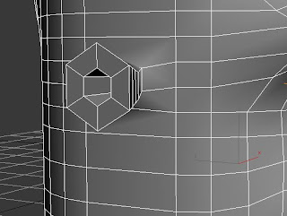
On the right side of the harness I edited the polygons I order to create a knife pocket. This can be seen in the image below.

Once the turbo smooth and a leather material has been added:


Creating the body

To create the body I began with placing a plane into the 3d Max scene. I then applied a bitmap image of a jumper with a male body figure onto the plane. I would then use this in order to shape and move around the vertex points to create the body.

I then placed a cylinder onto the scene on top of the plane with the image on.

I converted the cylinder into an editable poly and deleted ¾ of the polygons leaving just the right hand top corner. I would then use this section to create the right hand corner of the jumper. Seeing as the jumper is symmetrical on both sides I could create 1 corner of the jumper and mirror the polygons.

I then moved the vertex points into line with the image on the plane.

Once the first quarter of the body was created and shaped I could now copy and mirror the shape to create the back of the jumper. This created the first half of the jumper. I used the same process to create the other half of the jumper.


Using the attach tool on the first section of the jumper I could now attach all of the sections together and using the weld tool, weld all of the vertex points together. The jumper now looks like the top of a male body.

It was necessary to perform some vital adjustments at this stage of the modelling process as once it was welded together it was much easier to identify any faults.

At this stage the body required bitmapping. I chose to use a wool material but in order for the material to fit on the body correctly I had to use an Unwrap UV modifier.

Using the unwrap UV modifier enabled me to stretch out the vertex points within the material editor so that material fitted onto the body without any of the material stretching in areas such as the neck and sides.

I made a copy of the UV map for reference so that I could edit the material in photo shop should I need to add  any logos or extras to the material on the body.